Hardware:
ALLEN-BRADLEY MICROLOGIX1400 DIGITAL PLC TRAINER
Software:
RSLogix 500 + RSlinx
Related Manual:
Micrologix 1400 Reference Manual
MicroLogix 1400 Programmable Controllers Installation Instructions
Target:
Use the Micrologix 1400 to achieve basic traffic light control.
Signal:
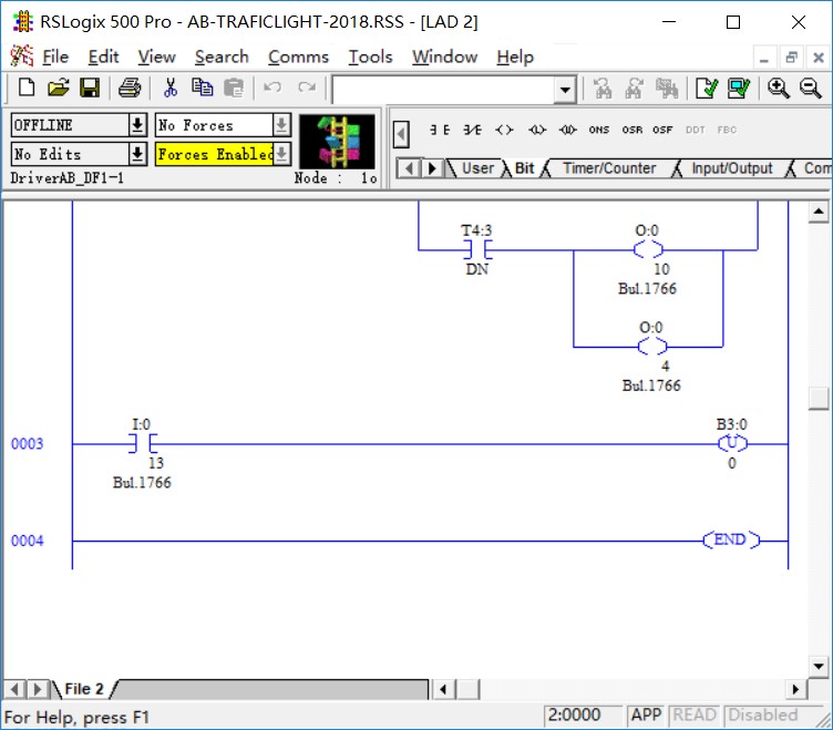
Digital Input I:0/12 and I:0/13
DIgital Output O:0/0 to O:0/11
Wiring:
We need two input signals: IN 12 and IN 13, so you need to connect these two to the PLC trainer I/12 and I/13 buttons.
And About output signals, You need to connect Out0 to Out11 to the PLC trainer O/0 to O/11 LEDs. COM2 need to connect to VDC NEUT, and connect the DC0 VAC, DC1 VAC, VDC2, DC3VAC, DC4VAC, DC5VAC to the VDC+24, in order to get power supply for the LEDs.
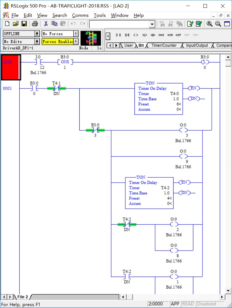
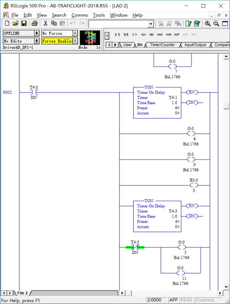
Program:
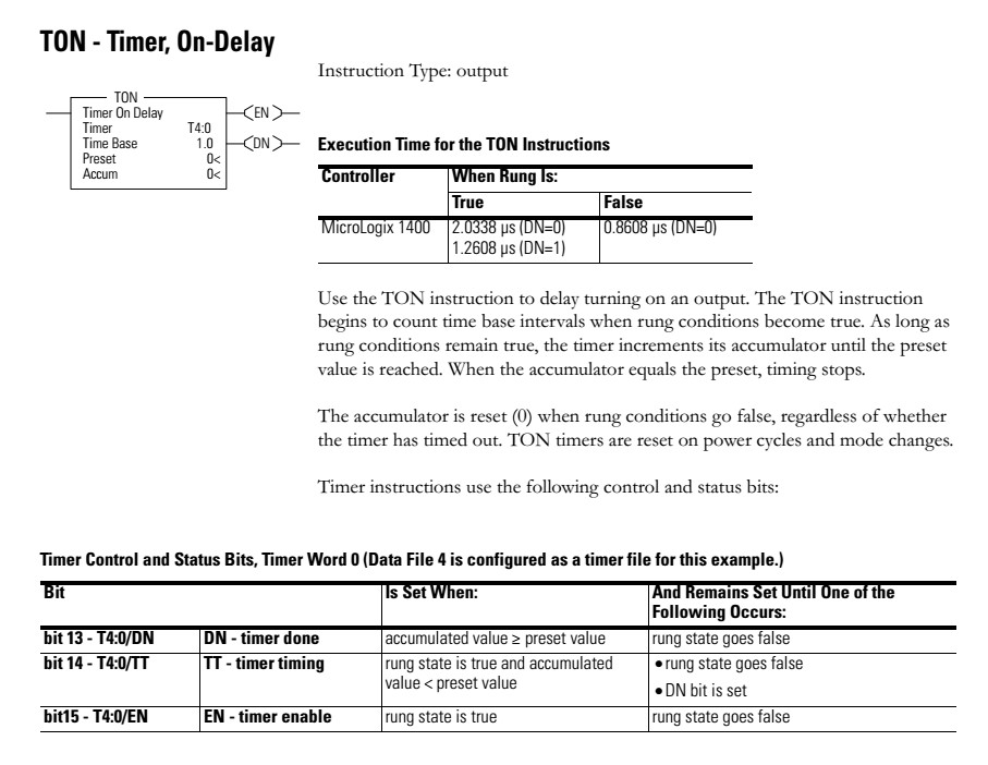
You can see, we use the TON instruction to control the delay time of the LED lighting.
T4:0 and T4:1 are used for controlling the whole red light cycle, which also equal to green light cycle + yello light cycle.
Red light time = Green light time + Yello light time
The T4:2 and T4:3 are just setting the green light time.
When T4:2 and T4:3 are not ON, the green lights will be powered on,
after 4 seconds, the T4:2 and T4:3 become ON, the green lights are off, and the yellow lights on for the last two seconds(6-4=2)